Home
Why on Mars?
Principle
Hardware
Animations
Links
People
Partners
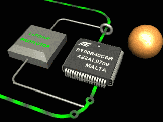
Electronic Hardware
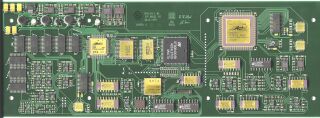
The heart of the electronics is a dedicated micro computer system. On power-up the required measurement software is automatically downloaded from the Lander computer. After receiving the commands and parameters for a new measurement, it starts taking images and sends this information back to the Lander computer. There are digital-to-analog converters and amplifiers to actuate the scanner. One of the eight sensor signals is chosen, amplified, analyzed and measured by an analog-to-digital converter. This signal is fed back by a software controller to control the distance or force. Many chips are added to generate and analyze the signals for the dynamic mode, such as a Direct Digital Synthesizer (DDS), a Phase Locked Loop (PLL) and an Automatic Gain Controller (AGC). All logic circuits are realized in two Field Programmable Gate Arrays (FPGA).
The design procedure for space electronics has to fulfill many special requirements.
During launch the rocket engines cause all the modules on the Phoenix Mars Lander Mission 2007 to vibrate. When parts of the space vehicle are separated by explosive charges, strong shock waves occur. The electronics must therefore be vibration tested to ensure that it will withstand these conditions. This board survived the vibration tests, because small lightweight parts were closely mounted on it and the board itself was rigidly bolted to MECA module frame. |
|||||
|
The Martian atmosphere consists mainly carbon dioxide at a pressure of only 7 millibars. These are very good conditions for direct atmospheric electrical discharges. Therefore all electrical voltages have to be limited to a maximum of 15 Volts. |
|||||
The Martian temperature sinks to -90 degree Celsius at midnight and rises to -10 degree Celsius only at noon. All electronic components on the board are specified to at least -40 degree Celsius, but the functionality of the board has been tested down to -100 degree Celsius. |
|||||
|
|||||
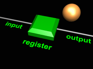
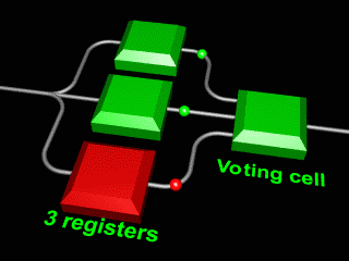
A major problem for electronics in space and on Mars is radiation. On Mars the solar radiation and bombardment with heavy ions is much less shielded than on Earth which has a magnetic field and a thicker atmosphere. There are different damage effects induced by radiation. Due to the relatively short mission duration, the accumulated radiation dose is not critical. If a heavy ion hits a register cell, the stored information will be destroyed, but the register itself will survive. This single event upset (SEU) can either cause a fatal error or this state can be recovered by the program.
All important register cells in programmable logic chips are implemented as triple voting registers. With this design rule the failure rate can be reduced by a factor of 1’000 to 10’000.
|
|||||
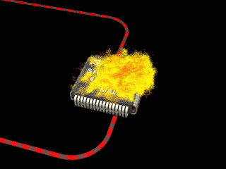
Unfortunately a more severe and fatal hardware failure can occur in certain CMOS chips. This phenomena is called a Single Event Latch-up (SEL), where a conducting path between a power line and ground is opened by a sudden ionization. A very high current will flow through this path and can destroy the CMOS chip.
|